High accuracy series
Flow meter VH02 · Flow controller VHC02
Metrology, R&D and demanding gas blending. Accuracy tiers are higher than the standard series across the full range.
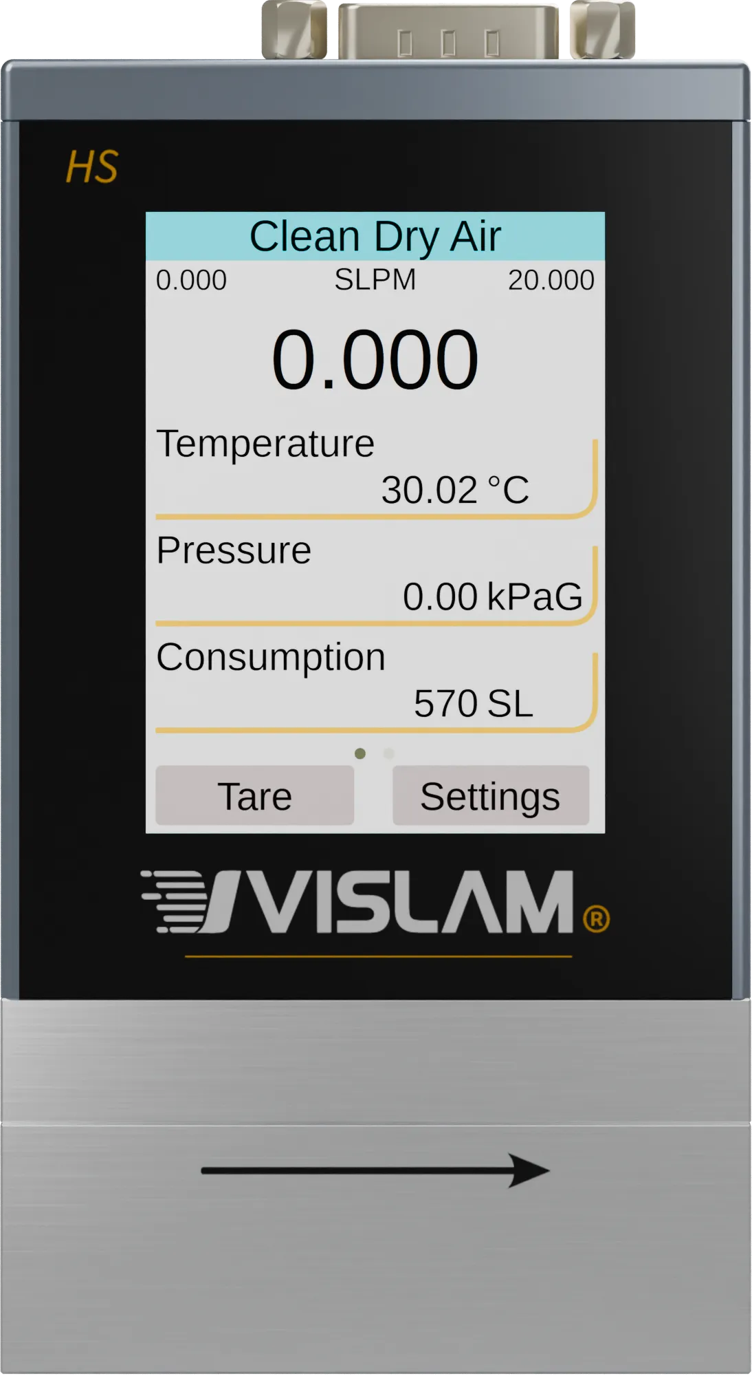
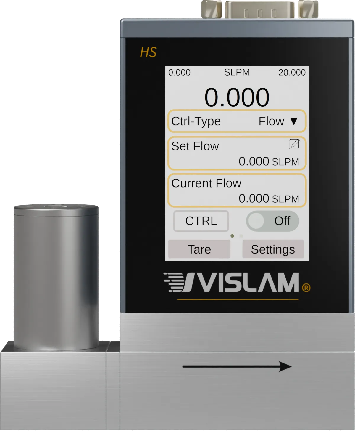
Specifications compared
The flow meter and flow controller share the same laminar differential pressure measurement platform; the controller adds a proportional valve and control functions.
| Item | Flow meter VH02 | Flow controller VHC02 |
|---|---|---|
| Range | 0.5 SCCM – 5000 SLPM | 0.5 SCCM – 500 SLPM |
| Accuracy (10 SCCM – 20 SLPM) | ±max(0.5%RD, 0.1%FS) | |
| Repeatability (10 SCCM – 20 SLPM) | ±max(0.1%RD, 0.02%FS) | |
| Turndown ratio | 1:1000, 1:10000 optional | |
| Response time | Measurement < 10 ms | Measurement < 10 ms; control as fast as < 100 ms |
| Warm-up | < 1 s to within rated accuracy | |
| Gas types | 124 (including humid air and predefined gas mixtures; no corrosive gases)See the list → | |
| Working pressure | 0–1.0 MPaG | |
| Max. withstand pressure | < 1.2 MPaG | 1.2 MPaG |
| Max. differential pressure | 0.6 MPaD | 1.2 MPaD |
| Operating temperature | −10 to 60 °C (expandable to −20 to 70 °C) | |
| Annual drift | <0.1%FS (in clean, non-corrosive gas) | |
| Power supply | 4.75 – 30 VDC; 2 W | 4.75 – 30 VDC; 0.5 SCCM – 20 SLPM: 5 W, 50 – 500 SLPM: 15 W |
| Power connector | USB Type-C, DB9 male | |
| Digital interface | Modbus RTU (RS485), USB (USB-to-serial) | |
| Analog I/O | 0–20 mA / 4–20 mA / 0–5 VDC / 1–5 VDC / 0–10 VDC (software selectable) | |
| Ingress protection | IP40 | |
| Wetted materials | 304 stainless steel, aluminum, gold, alumina ceramic, glass, epoxy, silicone, silicon | 300-series stainless steel, 400-series stainless steel, aluminum, gold, alumina ceramic, glass, epoxy, silicone, silicon |
| Seal material | FKM standard; EPDM, NBR and others optional | |
Accuracy and repeatability
Tiers follow the nominal full scale of the model, not the current reading. RD: reading; FS: nominal full scale; max: the larger of the two terms. These figures apply after flow zeroing, with temperature, pressure and humidity in equilibrium.
| Range | 0.5 SCCM – 5 SCCM | 10 SCCM – 20 SLPM | 50 SLPM – 5000 SLPM |
|---|---|---|---|
| Accuracy | ±(0.5%RD + 0.2%FS) | ±max(0.5%RD, 0.1%FS) | ±(0.5%RD + 0.2%FS) |
| Repeatability | ±(0.2%RD + 0.02%FS) | ±max(0.1%RD, 0.02%FS) | ±(0.2%RD + 0.02%FS) |
| Range | 0.5 SCCM – 5 SCCM | 10 SCCM – 20 SLPM | 50 SLPM – 500 SLPM |
|---|---|---|---|
| Accuracy | ±(0.5%RD + 0.2%FS) | ±max(0.5%RD, 0.1%FS) | ±(0.5%RD + 0.2%FS) |
| Repeatability | ±(0.2%RD + 0.02%FS) | ±max(0.1%RD, 0.02%FS) | ±(0.2%RD + 0.02%FS) |
Process connections
All ports are female threads.
| Flow Range | Standard Port | Optional Ports | Venting Pressure Drop |
|---|---|---|---|
| 0.5 – 5 SCCM | G1/8 | M5, PT1/8, NPT1/8 | < 6.5 kPaD |
| 10 SCCM – 20 SLPM | G1/8 | PT1/8, NPT1/8 | < 10 kPaD |
| 50 – 100 SLPM | G1/4 | PT1/4, NPT1/4 | < 10 kPaD |
| 250 SLPM | PT1/2 | G1/2, NPT1/2 | < 12 kPaD |
| 500 – 1000 SLPM | PT3/4 | G3/4, NPT3/4 | < 15 kPaD |
| 2000 – 3000 SLPM | PT1 | G1, NPT1 | < 20 kPaD |
| 5000 SLPM | PT2 | G2, NPT2 | < 20 kPaD |
| Flow Range | Standard Port | Optional Ports | Inlet Pressure Range |
|---|---|---|---|
| 0.5 – 100 SCCM | G1/8 | PT1/8, NPT1/8 | 20–1000 kPaG |
| 200 SCCM – 1 SLPM | G1/8 | PT1/8, NPT1/8 | 30–1000 kPaG |
| 3 – 10 SLPM | G1/8 | PT1/8, NPT1/8 | 50–1000 kPaG |
| 20 SLPM | G1/8 | PT1/8, NPT1/8 | 100–1000 kPaG |
| 50 – 100 SLPM | G1/4 | PT1/4, NPT1/4 | 100–1000 kPaG |
| 250 SLPM | PT1/2 | G1/2, NPT1/2 | 300–900 kPaG |
| 500 SLPM | PT3/4 | G3/4, NPT3/4 | 350–650 kPaG |
Venting pressure drop: the pressure difference between inlet and outlet at nominal full-scale flow, with dry air at 20 °C and 0.1 MPaA, the outlet open to atmosphere and the inlet connected to the gas supply. Inlet pressure ranges are given for standard models at nominal full-scale flow with the outlet vented, and can be customized on request.